URL: https://multiphasesystems.online/mfs2026.3.017,en
DOI: https://doi.org/10.21662/mfs2026.3.017
2Birsk Branch of the Ufa University of Science and Technology, Birsk, Russian Federation
Abstract
Currently, hydrocarbon production on the continental shelf faces serious problems: accidental fluid releases cause environmental damage, and hydrate formation in pipelines poses another major threat. Gas hydrates form at great depths under specific thermobaric conditions; they gradually narrow pipe passages and can fully clog them, leading to accidents and costly repairs. An underwater dome-separator installation with coaxial vertical channels is proposed to address these issues. It enables hydrodynamically separate extraction of oil and associated gas from spill zones or emergency well mouths, boosting collection efficiency and allowing control over hydrate formation. The study’s purpose was to build a mathematical model of multiphase mixture flow in the inner channel and identify conditions for gas hydrate layer growth. The model relies on equations describing heterogeneous media mechanics, convective heat transfer, and phase transitions. The resulting system of nonlinear partial differential equations — capturing velocity, pressure, temperature profiles, and hydrate crust thickness dynamics — was solved numerically using the Runge–Kutta method. Parametric modeling uncovered a key effect: hydrate layer thicknessand growth intensity vary nonmonotonously along the channel due to complex thermal and hydrodynamic interactions. Mass flow rates of the phases help control the risk zone’s location: higher oil flow shifts hydrate formation onset closer to the channel entrance, while increased gas flow moves it downstream. Key conclusions: critical channel narrowing depends on the balance of phase mass flow rates and the external coaxial channel’s radius. These findings provide a scientific basis for designing safe, fault-tolerant underwater mining systems and developing algorithms to prevent deep-sea pipeline blockages — crucial for offshore field development.
Accepted: 1.07.2026
Published: 30.09.2026
Stolpovsky MV, Nasyrov AA, Chiglintsev IA. Numerical Simulation Of Gas And Oil Extraction From A Dome-Separator Using A System Of Coaxial Cylindrical Channels. Multiphase Systems. 2026;21(3):108–116 (in Russian).
gas hydrate;
coaxial pipeline;
dome separator;
multiphase flow;
heat transfer;
numerical simulation
The work was supported by the state assignment of the Ministry of Education and Science of the Russian Federation on the topic ”ew methods for obtaining multifunctional organic compounds with a set of valuable properties (corrosion inhibitors, antioxidants, surfactants, plasticizers, etc.), processing multiparameter data from natural observations of monitoring water bodies and hydrate formation” (FEUR-2026-0004).
Article outline
Purpose of the work
The article discusses a significant issue in the field of underwater hydrocarbon extraction – accidental emissions and hydrate formation within discharge pipelines. These occurrences pose serious risks: unintentional emissions may cause substantial damage to marine ecosystems, while hydrate formation has the potential to gradually reduce the diameter of pipe sections until they become completely obstructed, leading to large-scale incidents and the necessity for complex and costly repair operations at significant depths.
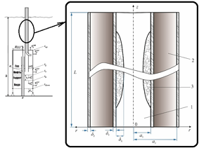
The authors propose utilizing a dome-type separator installation equipped with a system of coaxial cylindrical passages, where gas (specifically methane) is transported via the inner passage and oil via the outer passage. This configuration facilitates the hydrodynamic separation of phases directly from the area of spillage or the wellhead, significantly enhancing the efficiency of hydrocarbon recovery and establishing the foundations for a controlled influence on the hydrate creation process.. The main objective of the study is to develop a mathematical model for the flow of gas and oil in a given system, determine the conditions under which gas hydrates may form on the inner walls of the gas conduit, and investigate the impact of key parameters such as mass flow rates of different phases and channel geometry on the process of hydrate formation.
Within the scope of this research, particular attention is given to analyzing how changes in flow rates and design features of the system influence the location and extent of hydrate accumulation. The findings obtained are intended to provide a scientific foundation for the design of more robust and resilient underwater mining systems. Additionally, they can contribute to the development of effective strategies for preventing emergency shutdowns of deepwater pipelines, which is crucial in light of the ongoing expansion of offshore oil and gas fields.
Methods and approaches
A number of assumptions have been made in order to describe the flow. The flow is assumed to be quasi-steady. The gas stream is composed of methane and water in vaporous and liquid form. Oil is assumed to be a single-phase, incompressible fluid. The temperature of the gas and oil entering the system is higher than the surrounding water temperature, which is considered constant.
The mathematical model is based on the principles of mechanics of multi-phase media, heat transfer, and phase transformations. The following equations have been formulated: the conservation of mass equation for gas (constant flow rate); the motion equation for gas taking into account frictional and hydraulic resistance forces; the energy balance equation for gas considering steam condensation and heat transfer with the walls; similar equations for oil flowing in the annular space; a condition for thermal equilibrium on the channel walls; an empirical relationship between the equilibrium temperature for methane hydrate formation and pressure; and an equation for the equilibrium vapor water concentration. Hydrate formation has been considered in two regimes: ”heat-balance regime“ - when there is sufficient moisture, the rate of hydrate growth is limited by the heat removal rate, and the wall temperature equals the equilibrium temperature for hydrate formation.; ”Moisture Deficiency Mode“ - When there is a lack of moisture, the process is governed by the transfer of water droplets onto the surface. The rate of growth of the hydrate layer is determined using the moisture conservation equation. A system of differential equations is then solved numerically using the fourth-order Runge-Kutta method.
The results
The calculations were conducted for a 1200-meter-long pipeline with inner and outer channel radii of 10 cm and 22 cm, respectively.
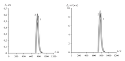
At the specified conditions (mass flow rates of 1.0 kg/s for gas and 6.0 kg/s for oil, inlet temperature of 310 K and gas pressure of 10 MPa), hydrate formation starts at a distance of approximately 700 meters from the inlet, with a length of the hydrate-forming zone of about 200 meters.
The temperatures of the gas and oil decrease monotonically along the channel, with the most significant drop in gas temperature and pressure occurring after the point of maximum channel constriction due to adiabatic expansion.
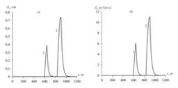
The thickness of the hydrate layer and its growth rate are non-monotonic along the length of the channel: they initially increase, reaching a maximum, before decreasing to zero due to the depletion of the water stream.. An increase in the oil flow rate (from 6 to 8 kg/s) results in an increase in hydrate formation intensity and a shift in the hydrate formation region closer to the inlet, due to increased heat exchange between the oil, gas, and surrounding water.
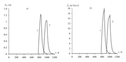
A corresponding increase in gas flow rate (from 0.5 to 1.5 kg/s) causes the hydrate formation region to shift further from the inlet, and also increases the thickness of the hydrate layer. This is because it takes longer for the gas to cool, resulting in more moisture in the system.
Additionally, an increase in outer channel radius (from 18 to 20 cm) leads to a shift in the beginning of hydrate formation, as well as an increase in layer thickness, due to the larger volume of oil that requires more time to cool.
The results of this study are significant for the design of safe subsea hydrocarbon production systems. Key control parameters include the mass flow rates of each phase and the radius of the external conduit. The model enables the prediction of the risk of hydrate-related pipeline blockages and the selection of modes that prevent the uncontrolled constriction of the conduit.
References
- Кильдибаева СР, Гималтдинов ИК. Теоретическая модель накопления углеводородов в куполе с учетом гидратообразования, лимитирующегося теплообменом. Известия Томского политехнического университета. Инжиниринг георесурсов. 2019;330(2):167–174. https://doi.org/10.18799/24131830/2019/2/117
Kildibaeva SR, Gimaltdinov IK. Theoretical Model for Hydrocarbon Accumulation in a Dome Taking Into Account Condensation, Limited by Heat Transfer. Bulletin of the Tomsk Polytechnic University. Geo Assets Engineering. 2019;330(2):167–174. (in Russian) - Гималтдинов ИК, Кильдибаева СР. К теории начального этапа накопления нефти в куполе-сепараторе. Теплофизика и аэромеханика. 2015;22(3):401–406. https://elibrary.ru/VUAXOL
Gimaltdinov I, Kildibaeva S. About the theory of initial stage of oil accumulation in a dome-separator. Thermophysics and Aeromechanics. 2015;22387–392. https://doi.org/10.1134/S0869864315030130 - Rui Z, Li C, Peng F, Ling K, Chen G, Zhou X, Chang H. Development of industry performance metrics for offshore oil and gas project. Journal of Natural Gas Science and Engineering. 2017;39:44–53. https://doi.org/10.1016/j.jngse.2017.01.022
- Archer D. Methane hydrate stability and anthropogenic climate change. Biogeosciences. 2007;4(4):521–544. https://doi.org/10.5194/bg-4-521-2007
- Шагапов ВШ, Мусакаев НГ. Динамика образования и разложения гидратов в системах добычи, транспортировки и хранения газа. М.:Наука; 2016. 320 с. (in Russian)
- Чиглинцев ИА, Насыров АА. Моделирование процесса наполнения купола-сепаратора с разложением газогидрата, образовавшегося в период монтажа установки. Инженерно-физический журнал. 2016;89(4):851–860. https://elibrary.ru/wfazlv
Chiglintsev IA, Nasyrov AA. Modeling of the Process of Filling a Dome Separator with the Decomposition of a Gas Hydrate Formed During the Mounting of the Installation. Journal of Engineering Physics and Thermophysics. 2016;89(4):854–863. https://doi.org/10.1007/s10891-016-1446-0 - Шагапов ВШ, Уразов РР. Характеристики газопровода при наличии гидратоотложений. Теплофизика высоких температур. 2004;42(3):461–468. https://elibrary.ru/OXKJSZ
Shagapov VSh, Urazov RR. The Characteristics of a Gas Pipeline in the Presence of Hydrate Deposits. High Temperature. 2004;42:463–470. https://doi.org/10.1023/B:HITE.0000033884.53813.1d - Бондарев ЭА, Рожин ИИ, Аргунова КК. Обобщенная математическая модель образования гидратов в магистральных газопроводах. Прикладная механика и техническая физика. 2019;60(3):120–127. https://doi.org/10.15372/PMTF20190312
Bondarev EA, Rozhin II, Argunova KK. Generalized Mathematical Model of Hydrate Formation in Gas Pipelines. Journal of Applied Mechanics and Technical Physics. 2019;60:503–509. \https://doi.org/10.1134/S002189441903012X - Pei J, Wei S, Wang Z, at al. A Quantitative Multiphase Flow Model Coupling Hydrate Phase Transition and Deposition in Long-Distance Subsea Pipelines. Chemical Engineering Science. 2026;332:124112. https://doi.org/10.1016/j.ces.2026.124112
- Leifer I, Boles JR, Luyendyk BP. Measurement of oil and gas emissions from a marine seep, development and technology. University of California energy institute (archive); 2007. 24 p. https://escholarship.org/uc/item/6ns670dt
- Chiglintseva AS, Nasyrov AA, Chiglintsev IA. Warm Insulation of Exhaust Pipe When Taking Gas From the ”Dome – Separator” Installation From Large Depths. IOP Conference Series: Materials Science and Engineering. 2020;860:012033. https://doi.org/10.1088/1757-899X/860/1/012033
- Кутателадзе СС. Основы теории теплообмена. 2-е изд., доп. М.:Атомиздат; 1979. 416 с.
Kutateladze SS. Fundamentals of Heat Transfer Theory. 2nd ed. M.:Atomizdat; 1979. 416 p. (in Russian) - Song GC, Li YX, Wang WC, Jiang K, Shi Z, Ye X, Zhao PF. Experimental study of hydrate dissociation in oil-dominated systems using a high-pressure visual cell. Journal of Natural Gas Science and Engineering. 2017;45:26–37. https://doi.org/10.1016/j.jngse.2017.04.032 https://doi.org/10.1016/j.jngse.2017.06.023
- Нигматулин РИ. Динамика многофазных сред. Ч. 1. М.:Наука; 1987. 464 c.
Nigmatulin RI. Dynamics of Multiphase Media. Vol. 1. Hemisphere, N.Y.; 1990. 532 p. - Уразов РР, Чиглинцев ИА, Насыров АА. Образование склеротических отложений гидрата в трубе для отбора газа из купола-сепаратора. Инженерно-физический журнал. 2017;90(5):1223–1231. https://elibrary.ru/znlkyv
Urazov RR, Chiglinstev IA, Nasyrov AA. Formation of Sclerotic Hydrate Deposits in a Pipe for Extraction of a Gas from a Dome Separator. Journal of Engineering Physics and Thermophysics. 2017;90(5):1162–1169. https://doi.org/10.1007/s10891-017-1670-2 - Norris BWE, Zerpa LE, Koh CA, Johns ML, May EF, Aman ZM. Rapid assessments of hydrate blockage risk in oil-continuous flowlines. Journal of Natural Gas Science and Engineering. 2016;30:284–294. https://doi.org/10.1016/j.jngse.2016.01.035
- Lou W, Sun D, Sun X, et al. High-Precision Nonisothermal Transient Wellbore Drift Flow Model Suitable for the Full Flow Pattern Domain and Full Dip Range. Petroleum Science. 2023;20:424–446. https://doi.org/10.1016/j.petsci.2022.11.011